
Alternative open source controller for popular JBC T245 soldering iron using Atmega 328p micocontroller and P-Channel mosfet. The main goal for this project was to learn more about using different types of Mosfets for driving soldering iron heating elements. Atmega 328p can be programmed using Arduino IDE and this controller uses the same firmware source as Atmega Soldering Station by Stefan Wagner. It is not binary compatible because the original board uses N-Channel mosfet but this project uses P-Channel mosfet. There is a configuration option for selecting the correct mosfet version in the firmware source code.
Features
- Based on Atmega 328p
- Arduino code by wagiminator
- P-Channel Mosfet
- I2C OLED display support (two pinouts supported)
- Buzzer
- DC/DC step-down power supply
- JBC T245 socket on the board
- FTDI UART header for programming and debugging
- 19-24V@5A DC power supply recommended
- Header for connecting rotary encoder separately
- 3,5mm terminal blocks for power and connecting soldering iron directly
- Sides of the board can be cut off if not needed
- Rotary encoder has some level of de-bounce resistance
Issues
- When heating up fast sometimes the controller reboots (19V 4,5A laptop PSU)
Resources
- Design files on GitHub
- Lots of interesting comments on the topic on Stefan Wagner’s project on OSHWLab website
Credits
Buy
- Bare PCB: 3€
-
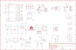
- Schematic

-

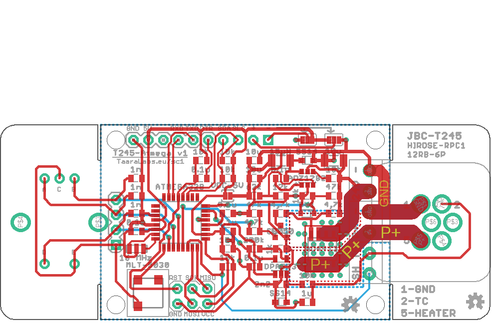
- Board layout
Notes and preferences
- Atmega 328p MCU is very familiar for electronic hobbyist and Arduino support is good. Unfortunately this MCU is hard to source since 2022.
- Eagle EDA free version for small projects is also very familiar for hobbyists and it’s file format is supported by many other packages.
- JBC T245 iron is not as popular and cheap as Hakko T12 but the availability of handles and cartridges in EU is better. The maximum power is greater and internal resistance is lower.
- Display, rotary encoder and socket for iron are on the same side of the board so that the board can be mounted on front of the box while PSU and power cord are on the back side.
- P-FET on high-side is easier do drive but the efficiency is typically lower than on N-FETS.
- N-FET on high-side needs a charge-pump circuitry to drive and while the N-FET itself has typically better efficiency the charge-pump is/seems to be not very efficient (diode and resistor gets hot)
- DC-DC step-down converter allows greater input voltage range (48V with TD1466)
- Single channel Op-amp is used to avoid extra resistors needed for two channel op-amps on the channels that are not used.
- Series resistor and reverse diode on the input of the Op-Amp are used for the protection against possible voltage spikes from the iron.
- Large ceramic input capacitor is smaller than electrolytic capacitor with same values would be but the ceramic capacitor “sings” audibly
- Parts are available either in EU (TME or Mouser) or China (LCSC).